


There are a number of conventions by which models in three dimensions are presented on a two-dimensional page. The following approaches do not involve perspective stereography.
1. Oblique Drawing
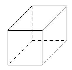
Figure 1. Oblique cube
In an oblique drawing, one of the co-ordinate planes of space is viewed directly facing the eye, while the dimension of the three-dimensional space that is perpendicular to that co-ordinate plane is on the page drawn obliquely halfway between the other two co-ordinate axis dimensions. Thus, the angle of the oblique dimension is half a right angle.
This oblique drawing is not a realistic representation of the shape of the model. In my view, the obtuse angle between the oblique and horizontal dimensions appears too large. Further, the oblique lines suggest the viewing of them at an inclination to the facing plane, and the projection of such inclined lines should cause them to appear shortened compared to those lengths facing the viewer. Thus, without this diminishing adjustment of oblique lengths, the back face of the cube by optical illusion appears deeper away from the eye than expected.
I am not fond of this type of oblique drawing, because one co-ordinate plane is drawn two-dimensionally while the third dimension appears like an after-thought. It could be used where one face or frontal view of the object or design is all-important, whereas the depth is merely incidental to the surface being mounted onto solid material of some kind of thickness.
2. Planometric Drawing
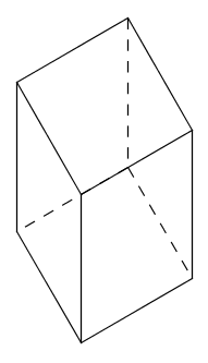
Figure 2. Planometric cube
In a planometric drawing, the top co-ordinate plane as viewed from above is facing the viewer and is undistorted, although it is rotated within its plane. The third dimension, which is the vertical one, is drawn at an angle of a third or two thirds of a right angle to the other co-ordinate axes. With re-orientation, this type of drawing, by maintaining one co-ordinate plane invariant, is like an oblique drawing but has the angle of the oblique lines as \(\pi/3\) or \(\pi/6\) rather than \(\pi/4\) radians. Thus, an obtuse angle between a vertical line and one of the top axes is a third of a turn.
In my view, the planometric drawing appears to be an improvement over the oblique drawing. However, without shortening of the vertical dimension, the cube by optical illusion appears taller than expected.
3. Isometric Projection
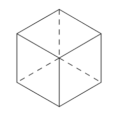
Figure 3. Isometric cube
An isometric projection is a more realistic representation of the model as though it were infinitely far away. The angles between any pair of axes in their projection on the page are all the same, and the axes have the same scales of length. Because the axes are inclined from the plane that is perpendicular to the line of sight, they should be drawn shortened from their true lengths in the model. The ratio of the true length in the three-dimensional model to the shortened length in the two-dimensional image projected on the page is as the ratio of lengths of sectors of a third and quarter turn inscribed in the same circle. In isometric projection, the obtuse angle between axes is a third of a turn.
Because of the importance and popularity of the isometric projection, a system of angular measure used for protractors should be capable of representing thirds of a full turn accurately. This means that the base of division of angle should be divisible by the number three. This is likely a reason for the retention of the two-and-a-half square dozen degrees in angular measure in defiance of the decimal base which is incapable of representing thirds of powers of ten without the introduction of rounding errors by terminating decimals or a finite number of steps.
It is clear from the angles used, which included 30 degrees, 45 degrees, 60 degrees, and 90 degrees, for the mentioned modes of drawing in construction graphics, that the protractor should be divisible by powers of both the numbers two and three.
The smallest base with this property is senary. However, for base six, the number of digits required after the fraction point in the representation of an eighth for the angle 45 degrees would be three.
The twice nine base is no better at representing eighths, and is even worse because it involves division of the circle into more sectors to do so.
On the other hand, the base twelve or dozen can easily and simply represent the desired angles. The smallest angle required, 30 degrees, is a twelfth of a turn. For the angle 45 degrees which is an eighth of a turn, in dozenal only two numerical figures are required after the fractional point.
1. Oblique Drawing
Figure 1. Oblique cube
In an oblique drawing, one of the co-ordinate planes of space is viewed directly facing the eye, while the dimension of the three-dimensional space that is perpendicular to that co-ordinate plane is on the page drawn obliquely halfway between the other two co-ordinate axis dimensions. Thus, the angle of the oblique dimension is half a right angle.
This oblique drawing is not a realistic representation of the shape of the model. In my view, the obtuse angle between the oblique and horizontal dimensions appears too large. Further, the oblique lines suggest the viewing of them at an inclination to the facing plane, and the projection of such inclined lines should cause them to appear shortened compared to those lengths facing the viewer. Thus, without this diminishing adjustment of oblique lengths, the back face of the cube by optical illusion appears deeper away from the eye than expected.
I am not fond of this type of oblique drawing, because one co-ordinate plane is drawn two-dimensionally while the third dimension appears like an after-thought. It could be used where one face or frontal view of the object or design is all-important, whereas the depth is merely incidental to the surface being mounted onto solid material of some kind of thickness.
2. Planometric Drawing
Figure 2. Planometric cube
In a planometric drawing, the top co-ordinate plane as viewed from above is facing the viewer and is undistorted, although it is rotated within its plane. The third dimension, which is the vertical one, is drawn at an angle of a third or two thirds of a right angle to the other co-ordinate axes. With re-orientation, this type of drawing, by maintaining one co-ordinate plane invariant, is like an oblique drawing but has the angle of the oblique lines as \(\pi/3\) or \(\pi/6\) rather than \(\pi/4\) radians. Thus, an obtuse angle between a vertical line and one of the top axes is a third of a turn.
In my view, the planometric drawing appears to be an improvement over the oblique drawing. However, without shortening of the vertical dimension, the cube by optical illusion appears taller than expected.
3. Isometric Projection
Figure 3. Isometric cube
An isometric projection is a more realistic representation of the model as though it were infinitely far away. The angles between any pair of axes in their projection on the page are all the same, and the axes have the same scales of length. Because the axes are inclined from the plane that is perpendicular to the line of sight, they should be drawn shortened from their true lengths in the model. The ratio of the true length in the three-dimensional model to the shortened length in the two-dimensional image projected on the page is as the ratio of lengths of sectors of a third and quarter turn inscribed in the same circle. In isometric projection, the obtuse angle between axes is a third of a turn.
Because of the importance and popularity of the isometric projection, a system of angular measure used for protractors should be capable of representing thirds of a full turn accurately. This means that the base of division of angle should be divisible by the number three. This is likely a reason for the retention of the two-and-a-half square dozen degrees in angular measure in defiance of the decimal base which is incapable of representing thirds of powers of ten without the introduction of rounding errors by terminating decimals or a finite number of steps.
It is clear from the angles used, which included 30 degrees, 45 degrees, 60 degrees, and 90 degrees, for the mentioned modes of drawing in construction graphics, that the protractor should be divisible by powers of both the numbers two and three.
The smallest base with this property is senary. However, for base six, the number of digits required after the fraction point in the representation of an eighth for the angle 45 degrees would be three.
The twice nine base is no better at representing eighths, and is even worse because it involves division of the circle into more sectors to do so.
On the other hand, the base twelve or dozen can easily and simply represent the desired angles. The smallest angle required, 30 degrees, is a twelfth of a turn. For the angle 45 degrees which is an eighth of a turn, in dozenal only two numerical figures are required after the fractional point.

» Dozenal Number Words from Metric Prefixes
» Dozenalizing Metric
» Myon Dozenal Nomenclature
» Information per Area of Numerical Forms
» Denominational Dozenal Numerals
» Proto-Indo-European Numbers
» Radix Economy for Alternating Bases
» Graduation Subdivisions